Difference between revisions of "Hardware: Frame Assembly"
(→Drill and Debur) |
(→Set Overload Limits) |
||
| (105 intermediate revisions by 3 users not shown) | |||
| Line 1: | Line 1: | ||
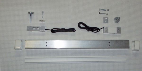
[[File:Chesick4.jpg|thumb|600px|Finished rails (load cell mounts). Two go under the hive, one on each side.]] | [[File:Chesick4.jpg|thumb|600px|Finished rails (load cell mounts). Two go under the hive, one on each side.]] | ||
[[File:Chesick5.jpg|thumb|600px|End view of rail with end cap and closure strip removed.]] | [[File:Chesick5.jpg|thumb|600px|End view of rail with end cap and closure strip removed.]] | ||
| − | == | + | ==Goals, Features, and Flaws== |
| − | + | For design goals, features and flaws, see the [[Frameless_Scale|Frameless Scale Design]] | |
| − | + | ==Parts List== | |
| + | Part numbers, suppliers and prices are on the [[Media:Chesick scale costs.pdf|Parts List]]. | ||
==Tools== | ==Tools== | ||
| Line 17: | Line 18: | ||
#10 mm wrench | #10 mm wrench | ||
#13 mm open end wrench | #13 mm open end wrench | ||
| − | #7/16" | + | #7/16" [http://www.amazon.com/SE-7909LP-9-Piece-Hollow-Leather/dp/B0002964CC/ hollow punch] |
#Feeler Gauge | #Feeler Gauge | ||
| + | #Small straight blade jewelers screwdriver. | ||
Optional tools: | Optional tools: | ||
| Line 25: | Line 27: | ||
#Stationary disk sander | #Stationary disk sander | ||
| − | == | + | <br clear=all> |
| + | |||
| + | ==Fabricate Rails== | ||
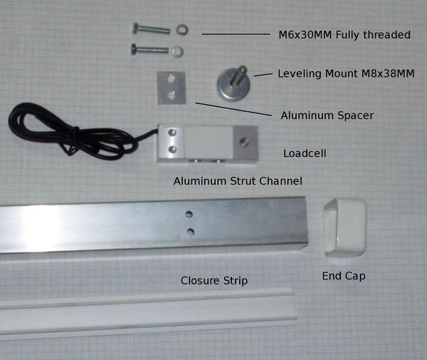
| + | [[File:Chesick2.jpg|thumb|600px|Parts Detail]] | ||
===Cut Strut=== | ===Cut Strut=== | ||
| − | Cut the strut in 20" lengths. Three can be cut from 5' strut, | + | Cut the strut in 20" lengths. Three can be cut from 5' strut, six can be cut from 10 foot lengths. The rails may be slightly less than 20" after losing the width of the saw kerf. Two 20" lengths will be needed to build one scale. |
#Mark the strut using a tape measure, If using a hack saw, transfer the marks around the strut using a layout square. | #Mark the strut using a tape measure, If using a hack saw, transfer the marks around the strut using a layout square. | ||
| Line 47: | Line 52: | ||
<br clear=all> | <br clear=all> | ||
| − | + | ==Assemble Rails== | |
| + | |||
| + | ===Mount Load Cells=== | ||
| + | [[File:Chesick1.jpg|thumb|600px|Exploded parts diagram.]] | ||
| + | |||
| + | |||
Turn a rail upside down with the open side up. Place a spacer over the holes. | Turn a rail upside down with the open side up. Place a spacer over the holes. | ||
Carefully position the load cell over spacer. Align the holes without shifting the spacer. | Carefully position the load cell over spacer. Align the holes without shifting the spacer. | ||
| − | '''NOTE: | + | <div style="background-color: yellow; font-weight: bold; font-family:arial;color:#FF0000;font-size:14px;text-align:center;">'''NOTE: The green arrow on the end of the load cell should point in the direction force will cause the load cell to flex.'''</div> |
Place a lock washer and flat washer on a M6x30mm bolt. While holding the load cell and spacer in place with one hand, start the bolt in one of the holes. Do the same for the other bolt. | Place a lock washer and flat washer on a M6x30mm bolt. While holding the load cell and spacer in place with one hand, start the bolt in one of the holes. Do the same for the other bolt. | ||
| − | Make sure the load cell is centered in the strut and not touching the sides. | + | Make sure the load cell is centered in the strut and not touching the sides. When you tighten the bolts, the end of the load cell will want to shift a little and could end up touching the sides. You may need to hold the load cell in the center of the strut while you tighten. |
| + | |||
Tighten the bolts. | Tighten the bolts. | ||
| Line 60: | Line 71: | ||
Screw the leveling feet all the way into the load cells. The leveling foot should go all the way through the load cell, but not touch the strut. | Screw the leveling feet all the way into the load cells. The leveling foot should go all the way through the load cell, but not touch the strut. | ||
| − | ====Cut Closure Strips | + | |
| + | <div style="background-color: yellow; font-weight: bold; font-family:arial;color:#FF0000;font-size:14px;text-align:center;">'''NOTE: having the leveling leg too close to the strut may result in errant readings.'''</div> | ||
| + | |||
| + | ===Cut Closure Strips=== | ||
Measure the distance between the leveling feet. | Measure the distance between the leveling feet. | ||
| − | Using the hacksaw, cut the closure strip to fit between the leveling feet. If the strip is cut too long, a rat tailed file or rasp can be use to cut a semicircle in the ends | + | Using the hacksaw, cut the closure strip to fit between the leveling feet. '''The closure strips should not contact the threaded portion of the leveling feet.''' If the strip is cut too long, a rat tailed file or rasp can be use to cut a semicircle in the ends. |
| − | + | ===Punch End Caps=== | |
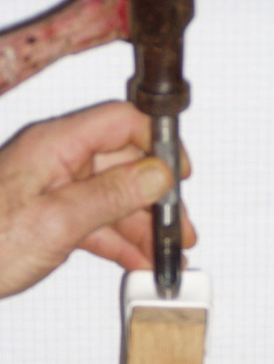
| − | + | [[File:Punch endcap1.jpg|thumb|400px|Punch End Caps]] | |
<br clear=all> | <br clear=all> | ||
| − | == | + | ===Set Overload Limits=== |
| − | |||
| − | |||
| − | |||
| − | |||
| − | == | ||
| − | |||
| − | |||
| − | + | ******** NO! DO NOT DO THIS! *********** | |
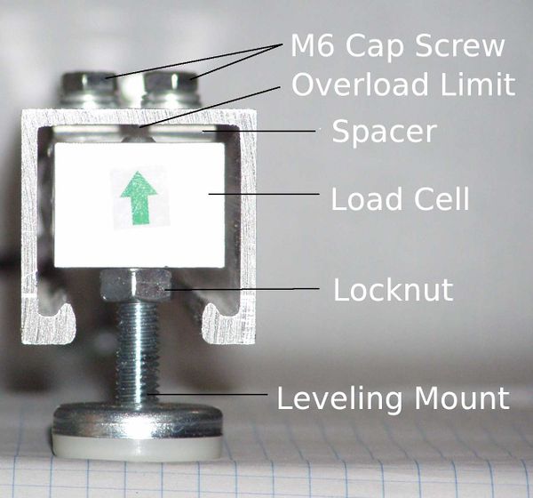
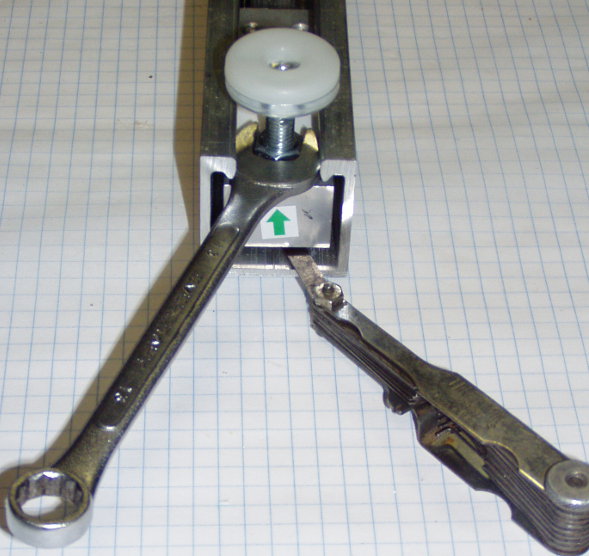
| − | + | [[File:Loadcell overlimit.jpg|thumb|600px|Setting the overload limit. '''NOTE THE LOAD CELL IS INSTALLED UPSIDE DOWN! WRONG! THE ARROW SHOULD POINT AWAY FROM THE FOOT.''']] | |
| − | # | + | <div style="background-color: yellow; font-weight: bold; font-family:arial;color:#FF0000;font-size:14px;text-align:center;">'''NOTE: This load cell is installed upside down! The green arrow on the end of the load cell should point in the direction force will cause the load cell to flex.'''</div> |
| − | |||
| − | |||
| − | |||
| − | |||
| − | |||
| − | + | Mechanical overlimit protection is not essential, but is a good idea. Overloading load cells beyond their capacity may damage them. They are typically rated at 120% to 150% overload capacity. See the Safe Overload rating on the [[Media:CZL602X.pdf|CZL602X Spec Sheet]]. Dropping a full super on top of the hive or forcing a frame into a super is usually not a problem, the wood will absorb most of the shock. | |
| − | + | '''If the scale is dropped onto a cement floor and hits on one corner or if not properly packed for shipping the load cells may be damaged.''' | |
| − | |||
| − | |||
| − | + | Mechanical overlimit protection consists of some method of limiting the travel (bending) when an overload is applied. | |
| − | |||
| − | |||
| − | |||
| − | + | #Insert a feeler gauge between the load cell and the top of the mounting rail. | |
| + | #Adjust the leveling foot until it contacts the feeler gauge. | ||
| + | #Tighten the lock nut so the leveling foot cannot move. | ||
| − | + | If the gap is set too narrow, the scale will not correctly record increases in weight. | |
| − | |||
| − | |||
| − | |||
| − | |||
| − | |||
| − | |||
| − | |||
| − | |||
| − | |||
| − | + | The size of the gap can be measured by attaching a dial gauge to the scale and loading it to capacity. | |
| − | |||
| − | |||
| − | |||
| − | |||
| − | + | For the CZL602X load cells, the proper gap appears to be about .002 inches. | |
| − | |||
| − | |||
| − | |||
Latest revision as of 11:54, 3 March 2020
Contents
Goals, Features, and Flaws
For design goals, features and flaws, see the Frameless Scale Design
Parts List
Part numbers, suppliers and prices are on the Parts List.
Tools
- Tape Measure
- Pencil
- Layout or speed square
- Hacksaw
- Drill
- 1/4" drill bit
- Center Punch
- File
- 10 mm wrench
- 13 mm open end wrench
- 7/16" hollow punch
- Feeler Gauge
- Small straight blade jewelers screwdriver.
Optional tools:
- Metal cutting band saw or cut off saw
- Drill press
- Stationary disk sander
Fabricate Rails
Cut Strut
Cut the strut in 20" lengths. Three can be cut from 5' strut, six can be cut from 10 foot lengths. The rails may be slightly less than 20" after losing the width of the saw kerf. Two 20" lengths will be needed to build one scale.
- Mark the strut using a tape measure, If using a hack saw, transfer the marks around the strut using a layout square.
- Carefully cut the strut on the lines, trying to keep as straight and square as possible.
Transfer Layout
Method 1:
- Place a load cell on the top of the rail. It should be about 4 mm (1/4") from the end. NOTE: If it is more than 4 mm from the end you will not be able to tighten the lock nut on the foot and the end cap will not cover the closure strip.
- Using a transfer punch, mark the two 8 mm mounting holes.
- Repeat on the other end.
- Check the punch marks to make sure they are in a straight line.
- Punch the marks deeper using the center punch.
Drill and Debur
Drill the four 1/4 holes in each rail to mount the load cells. Use a file, deburring tool, or stationary disk sander to clean up the ends. They will be covered by the End Caps so they don't have to be perfect. Use a file or deburring tool to debur the holes.
Assemble Rails
Mount Load Cells
Turn a rail upside down with the open side up. Place a spacer over the holes.
Carefully position the load cell over spacer. Align the holes without shifting the spacer.
Place a lock washer and flat washer on a M6x30mm bolt. While holding the load cell and spacer in place with one hand, start the bolt in one of the holes. Do the same for the other bolt. Make sure the load cell is centered in the strut and not touching the sides. When you tighten the bolts, the end of the load cell will want to shift a little and could end up touching the sides. You may need to hold the load cell in the center of the strut while you tighten.
Tighten the bolts.
Thread an 8 mm hex nut on each leveling foot.
Screw the leveling feet all the way into the load cells. The leveling foot should go all the way through the load cell, but not touch the strut.
Cut Closure Strips
Measure the distance between the leveling feet.
Using the hacksaw, cut the closure strip to fit between the leveling feet. The closure strips should not contact the threaded portion of the leveling feet. If the strip is cut too long, a rat tailed file or rasp can be use to cut a semicircle in the ends.
Punch End Caps
Set Overload Limits
******** NO! DO NOT DO THIS! ***********
Mechanical overlimit protection is not essential, but is a good idea. Overloading load cells beyond their capacity may damage them. They are typically rated at 120% to 150% overload capacity. See the Safe Overload rating on the CZL602X Spec Sheet. Dropping a full super on top of the hive or forcing a frame into a super is usually not a problem, the wood will absorb most of the shock.
If the scale is dropped onto a cement floor and hits on one corner or if not properly packed for shipping the load cells may be damaged.
Mechanical overlimit protection consists of some method of limiting the travel (bending) when an overload is applied.
- Insert a feeler gauge between the load cell and the top of the mounting rail.
- Adjust the leveling foot until it contacts the feeler gauge.
- Tighten the lock nut so the leveling foot cannot move.
If the gap is set too narrow, the scale will not correctly record increases in weight.
The size of the gap can be measured by attaching a dial gauge to the scale and loading it to capacity.
For the CZL602X load cells, the proper gap appears to be about .002 inches.

