Difference between revisions of "Hardware: PCB Assembly"
(→Parts) |
(→Assembly) |
||
| Line 22: | Line 22: | ||
#Install RJ1 and RJ2. Be very careful to check that all the leads are in the holes before you snap it in place. | #Install RJ1 and RJ2. Be very careful to check that all the leads are in the holes before you snap it in place. | ||
#Install 1x4 and 1x6 male header. | #Install 1x4 and 1x6 male header. | ||
| + | #Install 1x4 and 1x6 female header on the make headers. | ||
| + | #Install the HX711 board on the 1x4 and 1x6 female headers. | ||
#Install LED. | #Install LED. | ||
#Install power supply if used. | #Install power supply if used. | ||
| Line 28: | Line 30: | ||
#Install four 1x2 male headers. | #Install four 1x2 male headers. | ||
#Install blue screw terminal block. | #Install blue screw terminal block. | ||
| − | + | #Install four 1x2 female headers on the four 1x2 male headers. | |
| + | #Install the Power Supply board on the four 1x2 female headers. | ||
power Supply 2 | power Supply 2 | ||
Revision as of 03:01, 18 January 2016
Contents
Parts
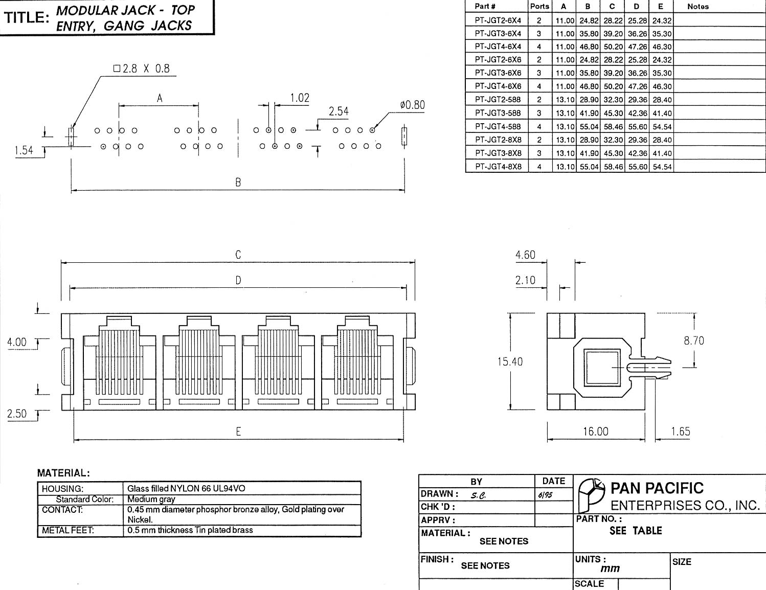
Mechanical Drawing for RJ connectors.
Board Layout
Assembly
- insert the 2x20 female header from the bottom side of the board.
- Solder the header on the top (component, silk screen) side of the board.
- Install the following resistors:
- R 330
- R 1K
- R 1K
- R 2.2K
- R 2.2K
- R 200K
- Install RJ1 and RJ2. Be very careful to check that all the leads are in the holes before you snap it in place.
- Install 1x4 and 1x6 male header.
- Install 1x4 and 1x6 female header on the make headers.
- Install the HX711 board on the 1x4 and 1x6 female headers.
- Install LED.
- Install power supply if used.
Power Supply 1
- Install four 1x2 male headers.
- Install blue screw terminal block.
- Install four 1x2 female headers on the four 1x2 male headers.
- Install the Power Supply board on the four 1x2 female headers.
power Supply 2
- Install Fulree voltage regulator
- Install green spring terminal block.