Difference between revisions of "Hardware: PCB Assembly"
(→Assembly) |
(→Assembly) |
||
| Line 28: | Line 28: | ||
|R1 | |R1 | ||
|330 | |330 | ||
| + | |Controls brightness of LED | ||
|- | |- | ||
|R2 | |R2 | ||
|200K | |200K | ||
| + | |12 V monitoring voltage divider | ||
|- | |- | ||
|R3 | |R3 | ||
|1K | |1K | ||
| + | |12 V monitoring voltage divider | ||
|- | |- | ||
|R4 | |R4 | ||
|2.2K | |2.2K | ||
| + | |12 V monitoring Reference voltage divider | ||
|- | |- | ||
|R5 | |R5 | ||
|2.2K | |2.2K | ||
| + | |12 V monitoring Reference voltage divider | ||
|- | |- | ||
|R6 | |R6 | ||
|1K | |1K | ||
| + | |Rain gauge input filter | ||
|} | |} | ||
Revision as of 07:15, 23 January 2016
Contents
Parts
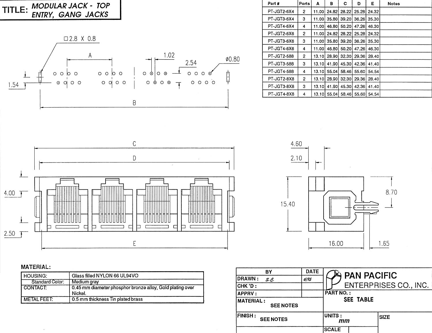
Mechanical Drawing for RJ connectors.
Board Layout
Assembly
1.Insert the 2x20 female header from the bottom side of the board.
- Error creating thumbnail: File missing
1.1 Insert the header from the bottom.
- Error creating thumbnail: File missing
1.2 Solder one pin on each end.
- Error creating thumbnail: File missing
1.3 Check the connector for alignment.
- Error creating thumbnail: File missing
1.4 Melt solder and straighten.
2. Solder the header on the top (component, silk screen) side of the board.
- Error creating thumbnail: File missing
2.1 Solder the rest of the pins.
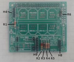
3. Install the resistors:
| R1 | 330 | Controls brightness of LED |
| R2 | 200K | 12 V monitoring voltage divider |
| R3 | 1K | 12 V monitoring voltage divider |
| R4 | 2.2K | 12 V monitoring Reference voltage divider |
| R5 | 2.2K | 12 V monitoring Reference voltage divider |
| R6 | 1K | Rain gauge input filter |
- Error creating thumbnail: File missing
1.1 Insert the resistors.
4. Install male headers
- H8 1x4 and H9 1x6 for the HX711 board.
- H4 1x4 for console serial port
1.2

- Install RJ1 and RJ2. Be very careful to check that all the leads are in the holes before you snap it in place.
- Insert the 1x4 and 1x6 female headers on the make headers.
- Install the HX711 board on the 1x4 and 1x6 female headers.
- Install LED D1.
- Install C1 4.7 mfd. Observe polarity.
- Install C3 .1 mfd. for rain gauge filter.
- Install 12 VDC power supply if used. See below for option 1 or 2.
Power Supply 1
- Install four 1x2 male headers.
- Install blue screw terminal block.
- Install four 1x2 female headers on the four 1x2 male headers.
- Install the Power Supply board on the four 1x2 female headers.
power Supply 2
- Install Fulree voltage regulator
- Install green spring terminal block.